Abstract Design
There are two major design concepts:
- Finite State Machine (FSM) that every channel implements. More accurately, every channel uses the same FSM implementation with their own instantiation guaranteeing identical behavior and no cross talk.
- A conceptual data flow for an ideal channel. It is instructive to understand the ideal flow then add the limitations and customization’s to the ideal for each channel later.
Finite State Machine (FSM)
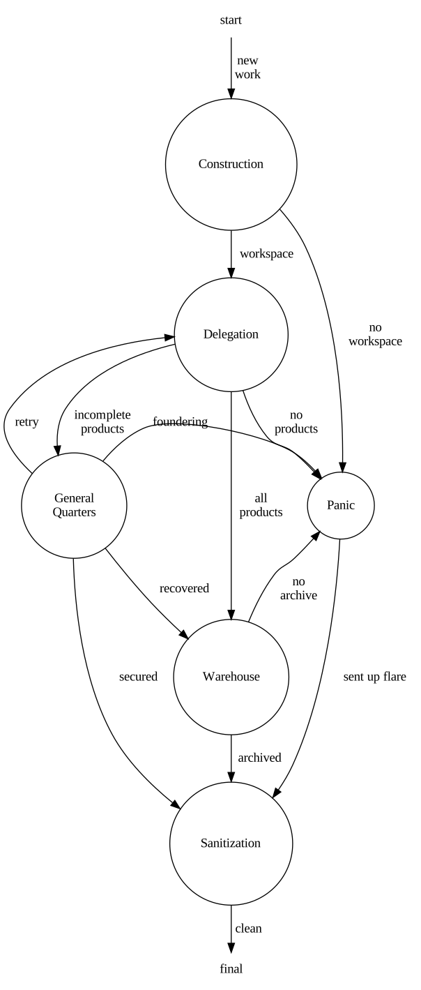
| State | Explanation |
|---|---|
| Construction | Create a workspace for shared content and specifically written information to avoid file lock issues with multiple processes accessing the same file at the same time. To conserve working space, Product data is not copied because two Delegations should not be transmuting the same products at the same time. |
| Delegation | Delegate a sandbox to a worker (DRP for all level Transmutations) in a sandbox. Wait for the worker to complete and transition to the next state depending on the what results are found. |
| General Quarters | Secure the log information. Review failure condition and attempt a recovery if possible. In all circumstances, generate a report and add it as an entry to the operational logs. Include if a recovery was attempted or not and what the recovery attempt was. |
| Panic | Secure the log information. Generate a report sending it as a flare – to everyone – and record it as an entry in the operational logs. |
| Sanitization | Remove the workspace. |
| Warehouse | Move any products in the workspace to the archival location. |
The FSM guarentees that the a sandbox is created, and mutable data is moved to that sandbox. Once the sandbox is established, corgidrp is used to process the data. The results are then warehoused or archived and the sandbox is cleaned up. Anomolous behavior is also captured by the FSM and depending on the severity of the anomoly different paths are taken. The important part is that a sandbox is always created and prepared then, no matter the full path, it is always cleaned up and removed. The FSM prevents resource leaks and enforces repeatible behavior through immutable data.
Ideal Channel

This is a data flow diagram with data moving from left to the right. Circles are actions or transmutations where the input data is transmuted to the output data through corgidrp.
Diagram Legend: | Feature | Explanation | | :—: | :— | | rectangle | Science information. Usually in the form of a FITS file. | | right block arrow | Calibration information. They are paths to files. Usually FITS. | | ellipse | Information produced by/for the DIP. | | circle | Action points where input data is transmuted to its output via corgidrp. | | dashed line | These information never enter the DIP universe. |
For the science data products the abstract design shows the lowest level (L1) data entering on the far left than being transmuted along the way to is highest level on the right (L4). Each transmutation leaves log information of what it did and generates a manifest of files it created. The manifest files are what DIP actually cares about and tracks.
The point of this approach is to make everything explicit. There are no hidden or implied anything in these diagrams. From looking at any specific channel, it should be obivous what information is needed as input and what will be produced and what is passed to generate the next product.
The entire DIP is then made up of similar diagrams that describe each channel (unique data types in the macro sense). The science data channels follow this pattern verbatum but change the generic calibration item to a list of actual calibration items. Hence, the images are far more detailed.
The calibration channels are far more abbriviated. Typically, they have the same calibration files as the science channel depending on what level of data is needed for generating the calibration product, but there will be one transmutation bubble instead a sequence of them.
There are a set of clerks as well. These, like calibration, are one bubble shows. Their whole existance is to organize the unruly world so that the DIP can flow the data through these diagrams. They take a set of L1 data and divide them into their channels. They load the calibration files and configuration information like output directories. While they do not perform any science tasks, it is important to organize the unruly world so that automatons like DIP can do their work unabated.
Calibration Channels
The calibration channels are simply abbriviated science channels because the corgidrp chains recipes to make the products.
Clerks
The clerks are tiny channels representing external information that flows in from XML files to become internalized within DIP for determining processing.
Summary
The DIP then executes the data flow represented by the detailed images using the FSM. There is no code to understand. There is only understanding and correctly representing the data flow in these diagrams ensuring the DIP flows the data as expected. The DIP, in turn then, is the sum of these images.